PART NO.  SPL.PAGE  DESCRIPTION
AEH589    TC.B.2    26 Pipe -ignition control -(vac.control, ignition, Twin Cam)-
    Fin.(E)2222 - no longer equired see service memorandum MG/301
2H3271    TC.B.2    27 Clip -(ign.ctrl.pipe, vac.control, ignition, Twin Cam) Fin.(E)2222-
    no longer required see service memorandum MG/301
    Twin Cam)
6K649     TC.B.2    28 Olive (2) -(ign.ctrl.pipe vacuum control, ignition, engine, Twin Cam)-
    Fin.(E)2222 -no longer required see service memorandum MG/301
2A459     TC.B.2    29 Nut carburetor end -(ign.ctrl.pipe, vac.control, ignition, Twin Cam)
    Fin.(E)2222 -no longer required see service memorandum MG/301
6K650     TC.B.2    30 Nut -distributor end -(ign.ctrl.pipe, vac.control, ignition, Twin Cam)-
    Fin.(E)2222 -no longer required see service memorandum MG/301
PCR0811   TC.B.2    31 Clip for pipe (fuel tap) -(ign.ctrl.pipe, vac.control, ignition, Twin
    Cam) -Fin.(E)2222 -no longer required see service memorandum MG/301
AEH589 Vacuum pipe for ignition control, and the vacuum controlled distributor, were used for early production MGA Twin Cam cars. Later production changed to a non-vacuum distributor, and the vacuum pipe assembly and associated parts were deleted. -- The drawing below is for parts identification only, and does not show final position and routing path of the vacuum pipe. Need more pictures for that.
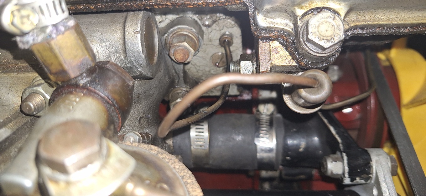
The picture below is incorrect, where the vacuum pipe appears to be screwed into the flange of the intake manifold, it should connect to bottom of the front carburetor.

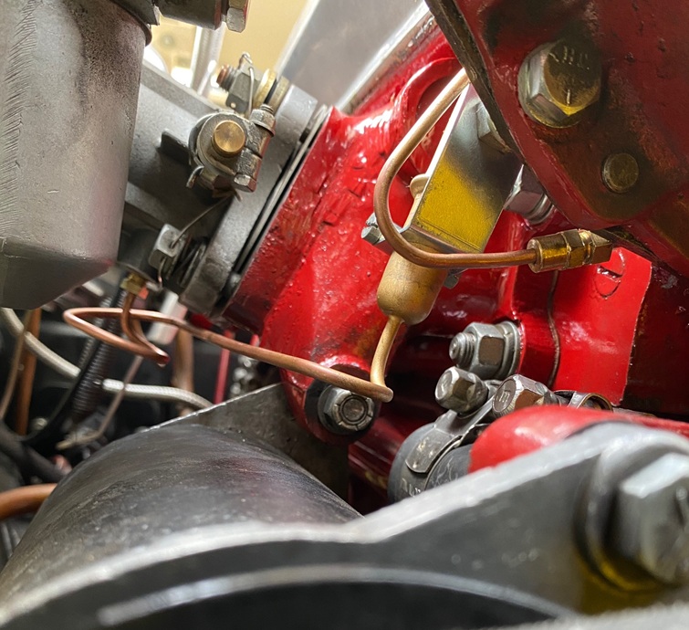
Picture below left is better. It does show the vcuum pipe connected to bottom of the front carburetor. it also shows the mounting clip for the fuel separator bulb properly attached to the rear of the engine front plate.
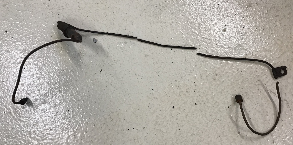
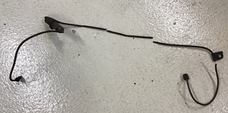
Below right is the complete pipe,rusty and broken in a few places. -- The Twin Cam vacum pipe is similar to the one for pushrod engines, using same mounting clips, but with longer pipes. The run from the trap to the carbs is only 1/2" longer but the trap to distributor run is 5.5" longer. Not including the trap: TC vs PR carb end 9" vs 8.5", and distributor end 23 3/8" vs 18". In photo below left, you can see a pipe extender splice joint just to right of the bulb bracket.

 Note from Mark Wellard in Australia:
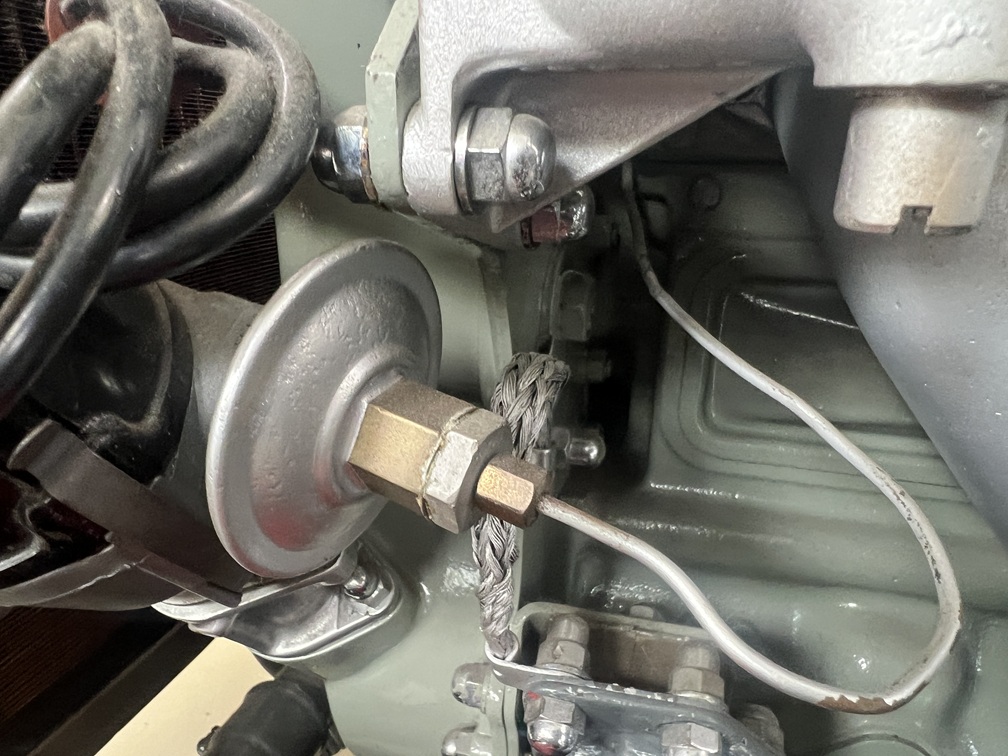
The fuel trap should be attached to the rear of the front engine plate adjacent to the front carby using the same type of clip as the pushrod trap, (although the SPL lists a P-clip). Mine was oriented at about 30-deg to horizontal. The line runs behind the front engine plate in the gap between it and the head. On the exhaust side it exits and joins the distributor which is adjacent to the exit point. When you see the SPL drawing it is a bit hard to sort out until you see the original, after which it makes sense.
|